Building the SoftRock Lite II SDR receiver.
By now you have either experimented with SDR yourself, or have read/seen articles about the technology. So I
wont go into a long explanation of what's involved here. There are several very good souces of information
can be found at Softrokcradio.org
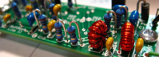
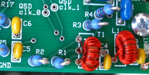
This comprehensive SDR reference is also well maintained. Winding the Toroids. Connecting the antenna.
I always wanted to construct an SDR kit, so I decided on Tony's SoftRock kit, since it has received so
much good press.
I ordered 2 x monoband kits (Softrock Lite II 40m, & 20m). Two days later I received 2 x kits in the mail. All components are included
with the two tiny PC boards. Assembly instructions are all found online here WB5RVZ.
This was my first attempt at construction using surface mount components(SMT) and was pleasantly surprised at how easy it went.
Make sure you have a good soldering iron (to ensure your project does not end in smoke) as well as a nice bench manifaying class
: to "see" what you're doing.
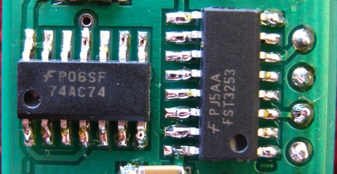
Soldering the 16 pin SMT IC's into place can be somewhat tricky, due to their small size and keeping them in location while soldering require some skill.
Once you've done a few, the process is actually very simple.
There are several good smt instructional videos online.
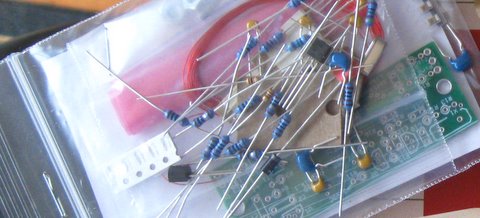 The kit arrives in a small plastic bag, and soon you will turn
this into a world-class HF receiver. The packaging of the parts make it easy to identify which belong where. Take good
care not to get the SMR caps mixed up. Tony marks these separate so you won't get them mixed up. Also the IC's are neatly
packaged separate from the other parts.
The kit arrives in a small plastic bag, and soon you will turn
this into a world-class HF receiver. The packaging of the parts make it easy to identify which belong where. Take good
care not to get the SMR caps mixed up. Tony marks these separate so you won't get them mixed up. Also the IC's are neatly
packaged separate from the other parts.
The board layout for SMT components is such that it makes for easy construction. This kit uses a few smt caps,
as well as 3 x multi-pin packages. The divider (14 pin 74AC74), muxer (16 pin FST3253 mux/demux switch) and a dual OP Amp.
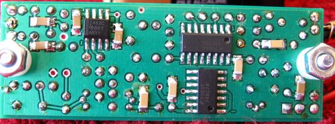
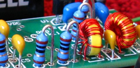
Good visual inspection of the smt soldering will go a long way towards troubleshooting.
The project assembly instructions,
are quite complete and provides Vdc checks after each construction stage. Make sure you
have a strong magnifying glass handy.
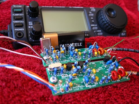
Once the board is complete, you'll have to hookup the power, antenna and audio connections. Make sure you follow
the instructions and pay special attention to the soundcard connections for I/Q signals.
SDR Software
Depending on the S/W you'll see the LO down the middle of the waterfall display. If you experience poor image rejection,
make sure that all the audio lines are connected properly, and the I/Q signals are feeding into the soundcard on the left/right
channels per the design doc. If your band is reversed, it means you have the I/Q signals swapped. Typically this can be
corrected by the S/W. Be sure to play around with S/W settings, as many different programs offer different features.

 The Rocky application provides very capable features for testing this
receiver. The waterfall display has very capable contrast settings, and it also sports a built-in BPSK31 decoder.
Left image is the 14.0 - 14.1 MHz view. Here you can see the waterfall displays for an active 20m band,
showing nice PSK traces as well as CW.
The image on the right is a zoomed view around 14.070MHz, showing various PSK31 and Olivia traces.
The Rocky application provides very capable features for testing this
receiver. The waterfall display has very capable contrast settings, and it also sports a built-in BPSK31 decoder.
Left image is the 14.0 - 14.1 MHz view. Here you can see the waterfall displays for an active 20m band,
showing nice PSK traces as well as CW.
The image on the right is a zoomed view around 14.070MHz, showing various PSK31 and Olivia traces.
24 HRS: Heard 234 stations in 12 countries (On a Tuesday).

Letting this receiver run for 24 hours using a 20m vertical antenna, yields some interesting resutls.
Heard 11 countries in under 24 hours! (Can you find another $10 reveiver which will do this?)


Here is a list of countries heard on during a 24 hr period on June 23rd 2009.
Freq: 14.070 PSK using DM780's internet auto-reporting facility.
Look at some of the distances..and this is on a Tuesday, when everyone is supposed to be at the office!
 And finally - a project box...Both 20m and 40m receivers go into a box about the size of your favorite antenna switch.
 And of course the vertical antenna to match this radio is the umbrella, vertical. It keeps the neighbors happy.
FieldDay 2009 On-Air results.

Over 1000 reports during the 24 hrs of ARRL Field Day (June 27 2009). Yello=20m, purple=40m. Antenna = wire vertical.

CW dead? This band has little space for anything in the CW section. 40m around 08h00 UTC is alive and well with Field Day activity.
Dead band - or just the end of Field Day?
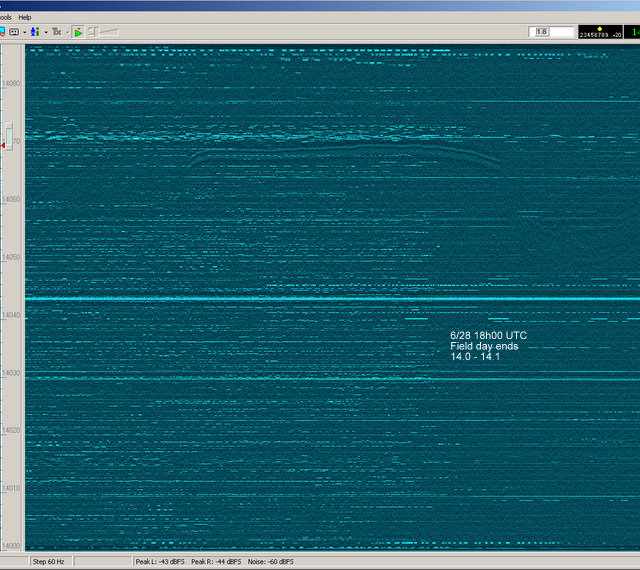
Have you ever wondered why propagation is so low and solar cycle 24 is just not happening? Maybe nobody's transmitting?
In this picture you can see what the end of ARRL Field Day 2009 looks like across the band section 14.0 - 14.1 MHz.
At 18h00 UTC, ARRL field day ended for those who started 24 hrs earlier, causing an evacuation of the band, appearing as if nothing is going on. This 30 minute
historical view tells the story of what happened leading up to the 18h00 timeframe.
Using a conventional receiver, tuning in at 16h05, you would think the band is dead...